The Ins and Outs Of VVT
June 25, 2012
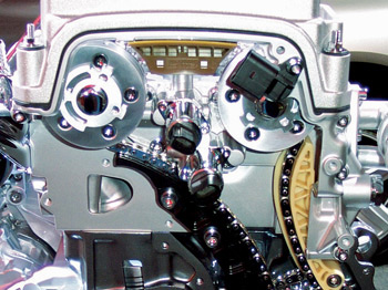
By the early 1990s, almost all import automotive manufacturers had a successful variable valve timing (VVT) system in production. These systems offered higher performance from smaller displacement engines at higher rpm.
As these vehicles exceeded their new car warranties, technicians learned the ins and outs of these systems and how regular oil changes could increase the life of VVT components. Now, the VVT is playing a direct role in vehicle emissions and the way gases are burned in the combustion camber.
 These systems are simple from a diagnostic perspective. Most VVT components are non-serviceable and have integrated sensors. But, they are part of a larger diagnostic picture that includes everything from the throttle body to the oxygen sensor.
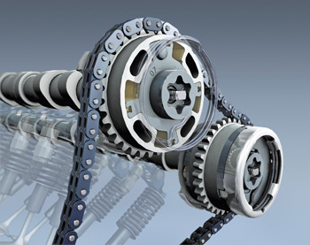
On a conventional engine, both the exhaust and intake valves’ open or closed position depends on their fixed position relative to the chain or belt that’s driven by the crankshaft. The pattern and timing cannot be altered, so there’s no way to increase or decrease the amount of valve lap when both valves are open at the same time.
As engines go, some have great low-end performance, while others have better top-end performance. (If you’ve ever heard an old street rod or dragster popping and rumbling at an idle, you’ve heard the lope from the cam. Because these engines are designed to have maximum performance at the top end, the cam is “cut” for better performance at the high end, so sacrifices are made at the idle end.)
With VVT, the valve duration can be matched to the engine speed, torque requirements and valve overlap. Now an engine can produce both low- and high-end performance without any erratic idle condition or high-end loss. This also enables an increase in miles per gallon throughout the engine’s power band by controlling valve timing and making the engine more fuel-efficient.
 One great advantage of the VVT system is the way it can take the force needed to expel the burnt mixture out of the exhaust valve. Pushing the exhaust gas out of a cylinder requires some of the force that is generated during the combustion stroke. Opening the exhaust valve when there is still some pressure left in the cylinder allows a small portion of the exhaust gas to escape before the piston starts its upward travel. This reduces the exertion from the crankshaft and piston and provides a smoother, more even-running engine at every rpm level.
Leaving the intake valve partially open at the right point also allows fresh air to enter the cylinder while the exhaust valve is doing its job of removing the already-burnt gases. This slight intake valve opening creates low pressure and aides the piston in pushing out the remaining gases and getting ready for the next turn of the crankshaft. This is all the result of the configuration and shape of the exhaust ports and manifolds, all of which work together and make the whole process seamless.
EGR AND VVT
One item that’s going the way of the smog pump is the Exhaust Gas Recirculation (EGR) valve. The elimination of the EGR valve is the result of the VVT’s ability to control gases entering and exiting the combustion chamber.
EGR systems are designed to reduce smog-causing nitrous oxides (NOx) by recirculating a portion of the exhaust gases from each cylinder of the engine back into the intake manifold. This process lowers the combustion temperature to under 2,500° F, above which NOx gases are formed, hurting both the environment and a vehicle’s performance.
 EGR systems work, but they are not able to react fast enough or precise enough for modern engines and emissions standards. Modern VVT systems are doing the same job as the EGV valve, only better.
A VVT system is able to control the timing of the exhaust valve so that the right amount of inert exhaust gases remain in the combustion chamber for the next combustion cycle. This controls combustion temperatures and the production of NOx.
If you encounter a vehicle that has higher than normal NOx levels, or a burnt or damaged pre-catalyst, make sure the VVT solenoid and exhaust camshaft position sensor are operating properly.
HONDA’S i-VTEC SYSTEM
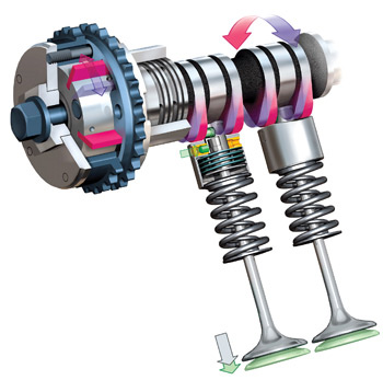
Honda’s term for a variable valve system is i-VTEC. The i-VTEC system uses an oil pressure solenoid activated electrically by the PCM to allow oil to pass into the rocker arm between the two normal rockers. This, in-turn, “locks” the normally used two intake valves together with a set of pins that are pushed outward into the two intake rockers and transfers their motion to a higher eccentric lobe (operated by the middle rocker arm). This higher lobe gives the engine the needed boost in power at an rpm higher than 4,500.
When the rpm level drops below 4,500, the oil pressure solenoid shuts off, blocking off the oil pressure and returns the engine to the normally operated two intake valves.
The 2008 Accord takes this to a whole new level of valve control, allowing the engine to go from six cylinders, down to four, and even down to three cylinders. It uses a solenoid to “unlock/lock” the cam followers on one bank and allows the followers to float freely while the valve spring keeps the valve in the closed position.
Vehicles equipped with Honda’s VCM (Variable Cylinder Management) systems also include Active Noise Cancellation (ANC) and Honda’s Active Control Engine Mount (ACM) system. The ANC and ACM systems work in cooperation to cancel both noise and vibration that could occur in relation to the cylinder deactivation process.
The ANC system uses the audio speakers to cancel out noise by incorporating an opposite phase sound. This whole process is controlled by the computer system and becomes imperceptible to the driver. These systems use a mechanical/electrical solenoid that operates with oil pressure to accomplish the range of variable valve timing.
The VTECE system is slightly different in its configuration than the VTEC. The emission qualities have been increased but, at the same time, it performs the same functions as the VTEC system.
TOYOTA’S VALVEMATIC SYSTEM
Toyota came out with the Valvematic system in 2008. This system uses an intermediate shaft to achieve a continuous variable valve lift. The intermediate shaft consists of followers on either side of a roller bearing. These followers rotate with respect to the roller member and “finger followers” (small followers) by means of an internal gear and electric motor attached to the shaft. As the shaft moves, the roller member and followers will move in opposite directions (either closer or farther apart). As the angle increases, so does the valve lift. This system can vary the valve timing to any angle needed.
In 2007, the VVT-ie system was introduced on the Lexus LS460. This system is both electrical and hydraulic. The exhaust valve is still controlled by way of an oil pressure solenoid, while the intake is controlled by an electric motor on the front of the cam. This allows valve timing to be adjusted with no regard to engine temperature or oil pressure.
COMMON VVT PROBLEMS
The two most common codes I’ve run across are P0011 and P0021 (Camshaft position sensor “Bank 1” and Camshaft position sensor “Bank 2,” respectively). These codes (like any code) don’t entirely mean the sensor is faulty, however the diagnostic charts will tell you to look at the VVT system for a fault and check the sensor as well. Some of the common areas to look into are: valve timing, oil control valve, oil control valve filter screen, camshaft timing/gears, and, of course, the electrical side of the operation as well as the PCM.
The very first thing I do before turning nuts and bolts is to check the oil. Oil is an essential part of most VVT systems. Dirty oil and the lack of regular oil changes can leave a buildup of sludge or debris in the passages that lead to the pressure control valve that operates the variable valve timing. If the oil is dirty and too much sludge accumulates at the valve ports, the sludge can be passed on through the cam and the valve assembly.
Then, the oil passages in the cam can be compromised and could result in a cam failure due to scored journals. Keep in mind that the VVT system is not operated at a normal driving condition rpm. For example, the Honda VTEC system doesn’t operate below 4,500 rpm. So, if you have someone who never gets the car out on the highway and never changes the oil, you can have a potential problem waiting to happen, if and when the car is revved up above 4,500 rpm the next time it heads onto an on-ramp of the local interstate highway.
Code P0521 (Oil pressure sensor/switch range/performance) could be an indication of the quality of the engine oil. It might not be the best diagnostic answer, but when I’ve seen this code on several vehicles, the oil was black and neglected. In some cases, the code can also indicate that the wrong type of oil has been used. I wouldn’t use this as the final solution to the problem with variable valve timing, but rather an indication of things to come.
Lack of regular maintenance seems to be the big factor in most of these systems. Unlike vehicles from years gone by where certain maintenance issues could be neglected, these newer engines and newer systems require the utmost in care. Stressing this point to your customers and performing the required basic maintenance per the manufacturer’s schedule will safeguard their vehicle and increase your profits.
FUTURE OUTLOOK
In my opinion, VVT will be as common as a spark plug in the near future. Reducing emissions and reducing the need for an EGR valve, improving fuel economy and getting more performance out of smaller engines tells me that the VVT systems are here to stay.
The next generation of VVT systems are on the drawing boards now, and it won’t be long before they’ll be in the marketplace. With the latest requirements in fuel economy emerging, engines with variable valve timing will become the norm, so it’s time to get ahead of the curve now.


