Mercedes-Benz: Managing Misfires, Solving Those Strange, Intermittent Engine Vibrations
June 11, 2012
By Sergio Fernandez. Real-life repair scenario: 2003 E320, with 3.2L V6 engine and 120,000 miles.
A customer brings his car into the shop with a “strange vibration.”
After we scanned the vehicle, we found the following DTCs: P0305, misfire on cylinder #5; and P0301, misfire on cylinder #1.
 The freeze-frame data in Generic OBD II gave us the following PID values: PRM = 800, ECT = 190, Eng. Load = 20%, VSS = 0 mph. The long-term Fuel Trim Value was near 0% and the Loop Status was Open.
After turning on the engine, we observed while the engine was at idle that the misfire or “strange vibration” as described by the customer was barely noticeable. No vibrations were felt when we raised the engine rpm while the vehicle was in Park and under no load. But, when returning to idle speeds after cracking the throttle, we started to feel the misfire.
We removed the 15-amp fuse #58 from the driver’s-side Signal Acquisition & Actuation Module (SAM). This fuse is designed to energize the six ignition coils. That way, we are able to control the current at every individual coil using a low-amp probe and an oscilloscope. The current drawn by each coil is twice that of a conventional coil because each double coil is energized by the PCM at the same time, but has two negative wires. The engine was running without misfiring.
During the moment that the misfire was not present, we sprayed a salt and water solution on the two suspected cylinders, #1 and #5, close enough in order to see the difference.
On most vehicles, wetting the ignition components may help to locate misfires because the electrolytes provide an alternate path to the spark to a ground without high resistance. You won’t be able to see the spark jumping to ground with this method because we are reducing the resistance to ground, making a direct connection with no air gap in between.
Some misfires do not happen long enough for the PCM to see the problem. The worst case is when this happens and the PCM does not recognize the particular cylinder and ends up setting a random misfire when we really have a miss in only one particular cylinder.
We did not have the factory tool to analyze this problem, which means we were unable to watch the PCM counting which cylinder was misfiring at that moment in the timing.
LAB SCOPE TESTING
We also decided to check the injector pulses using a lab scope. The power to the injectors comes from the 15-amp fuse #43 at the driver’s-side SAM. This fuse is shared in this particular vehicle with some other devices like the CAM sensor and the PCM, so the waveform was going to be very difficult to see and to understand. We decided to check just the pulses at two known-good cylinders, like #6 and #3, and the two suspected cylinders, #1 and #5.
As we know, the injector duration for each cylinder is calculated by the PCM according to the Mass Air Flow sensor signal (incoming air volume) or the Manifold Absolute Pressure (vacuum at the intake) and the engine speed. This basic calculation is modified (when the system is in closed loop) by a program called Long Term Fuel Trim (LTFT). These calculations are constantly modified by instantaneous adaptive values.
These adaptive values are the Short Term Fuel Trim (STFT) values, and are based on oxygen sensor signals, coolant temperature, air temperature, battery voltage and throttle position. When the PCM recognizes a 200-rpm misfire in one cylinder, the PCM must cut the injector pulse out in that cylinder to prevent the catalytic converter from receiving unburned gasoline and oxygen. As we know, when one cylinder misfires it becomes an “oxygen pump” and can destroy the catalytic converter in just hours if the PCM does not take any action with the fuel.
We had very good injector pulses in the four cylinders mentioned above, but after the misfire returned, the pulses at cylinders #1 and #5 disappeared.
Remember this scenario is normal. In some cases, technicians believe the PCM is bad because they see the injector pulses suddenly disappear when using a noid light. I don’t agree with the use of a noid light to check the injector pulse in a suspected misfire cylinder with the engine running, because although the cylinder is working properly, we “induce” that cylinder to misfire, and, obviously, the PCM will take the action because it was designed to “cut the injector pulse out” in front of a 200-rpm misfire.
It’s beneficial to use the noid light only when you need to see if you have injector pulses at cranking when the engine does not start (in other words, when the engine cranks but will not start). A lab scope is the right tool to use when the engine is running. While it’s a more expensive tool, it provides a lot more information by just touching one wire in a non-invasive way.
If the injector pulse cuts off from that cylinder, I should see a flat line and 12 volts, which means the power to the injectors is present. Also, I will see the voltage lows as a result of when the other injectors open and close. I won’t know what’s missing if I use a noid light.
COMPRESSION TEST

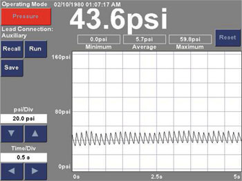
Chart 1
Then we did a commonly used compression test in all the cylinders with satisfactory results. All cylinders had the same compression, around 180 psi. Then, we performed a dynamic compression test using the Bosch MTS 5200 Engine Analyzer.
Chart 1 shows the result of the dynamic compression test of cylinder #3, which is far from being the suspect cylinder.
Remember the test we are conducting is a dynamic test, with the engine running and the result is going to be approximately 30% of the value that we generally see in a normal cranking compression test. When the engine is running, there is vacuum into the intake manifold and the cylinders cannot breathe (in the same way as when it’s cranking with the butterfly completely open).
Note: When you do a normal compression test, you are checking cylinder sealing, not cylinder breathing.
Think the engine is running at 18 inches of vacuum? The atmospheric pressure is about 30 inches at “sea level.” This means the difference is what the engine is sucking in (30 – 18 = 12 inches). Twelve inches of mercury is the same as 6 psi of absolute pressure. When this pressure is compressed at an 8:1 ratio, we should get 48 psi ( 6 x 8 ) of pressure if all the air goes into the cylinder (very important) and is pushed out. The idle reading on a dynamic compression has to be about 50 psi.
If we open the throttle, the atmospheric pressure goes into the intake manifold and the pressure increases. The reading also increases because the engine is able to breathe freely.
Note: Do not keep the engine running for a long time during this test, since the engine temperature will rise. Disconnect the injector in that cylinder and ground the plug wire that corresponds to the cylinder you’re checking.

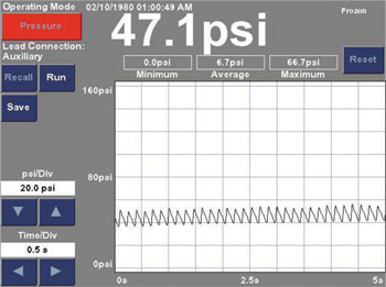
Chart 2
If one cylinder reads low during dynamic compression compared with the rest, it means the air could not be compressed or could not flow freely into the cylinder.
Chart 2 shows the result of the dynamic compression test of cylinder #5, which is the suspected cylinder. The #5 and #1 cylinders were the misfiring cylinders.
Note how it’s difficult to see any difference between the good and bad cylinder?
Then, we decide to perform an Engine Mechanical Health Condition Test using the vacuum transducer connected to the intake manifold, so we can see the amount of vacuum created by each engine cylinder. This information is displayed as either a high-resolution waveform or a percent per cylinder bar graph. I prefer the high-resolution waveform (used in this article) because it gives me more information (when a car is having a mechanical misfire) than the percent per cylinder bar graph. The bar graph shows the downward pike.

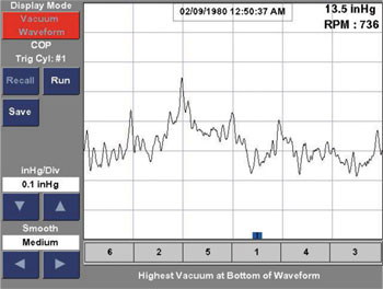
Chart 3
Chart 3 shows the Engine Mechanical Health Condition Test with the engine running and after a few minutes at idle.
The high vacuum (low pressure) is shown as a downward slope and low vacuum (high pressure) is shown as an upward slope.
The vacuum waveform display mode allows us to view the vacuum waveform that is produced by the intake stroke of each cylinder. The cylinders are listed in the order of the engine’s intake events (which is the same as the firing order).
Vacuum is formed by the downward movement of the pistons during the intake stroke. If the cylinder is sealed, a maximum amount will be formed. High vacuum improves volumetric efficiency. A normally running engine produces a uniform amount of vacuum on each cylinder.
The average intake manifold level and the engine rpm are showed in the upper right portion of the screen (see Chart 3). The average vacuum manifold level displayed for this car is 13.5 inHG, which is low.
Vacuum reading can be interpreted to identify many engine conditions, including the ability of the engine to seal, the timing of the opening and closing of the engine’s valves, and the ability of the engine to breathe. Once again, we are checking only the Engine Mechanical Health Condition.
Ideally, each cylinder on an engine will produce the same amount of vacuum; therefore, the vacuum reading must be equal/even. The waveform should not present any difference, either in the lower portion or the higher portion. Notice in the chart that cylinder #5 is creating less air than the rest of the cylinders, but the engine does set up the misfire at this moment, so the problem is not felt by the PCM yet.

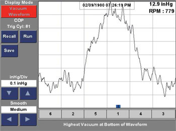
Chart 4
A normal vacuum gauge will be steady at this moment, but see Chart 4 where we raised the engine rpm and the kept the engine running. Pay attention to cylinders #5 and #1 in the waveform.
Chart 4 shows the Engine Mechanical Health Condition Test with the engine at idle right after the rpm went down.
As you can see, cylinder #5 is unable to create the right amount of vacuum because the exhaust valve spring from that cylinder was broken (yes, it was broken). The next cylinder (“according the firing order”), #1 is also unable to create vacuum due to the problem in cylinder #5 that has left air in the intake manifold. That air was not pumped into the cylinder as it should be, but cylinder #5 had a very good result in the compression test; it had the same value as the rest of the cylinders. Remember, when we do a compression test, with either dynamic or normal cranking, we are checking cylinder sealing, not cylinder breathing.
Note: When you have a misfire in two cylinders that are followed by the firing order, focus diagnostics at the first one; the second one may not be the cause of the problem.
During the compression tests (either dynamic or normal), we found no problems or noticeable differences between a known-good cylinder and the suspected one, because each cylinder compresses the air that gets in regardless of its source. The compression gauge, whether an expensive or inexpensive one, shows the pressure built by the cylinder.
It does not analyze the origin of the gas being measured. It does not care where the air is coming from; it can arrive “good”from the intake manifold or it can come from the exhaust valve, which used to open a bit because of the vacuum created by the cylinder during the admission stroke.
The vacuum transducer takes a measure of the amount of vacuum created by each cylinder and its waveform is synchronized with the spark to show which cylinder is or is not sucking more or less air. If one cylinder drags less air than the rest, you will be able to see which one is causing the problem. It takes just few minutes to configure the transducer, then read the waveform with attention to these details.
In Conclusion: A compression test, whether static or dynamic, is not always reason enough to pass an engine mechanical condition when an external problem (i.e. ignition, fuel, etc.) is not found.


