Fuel Systems
THE FILLING STATION

WHAT ABOUT ALCOHOL CONTENT?
FUEL QUALITY TEST
alternative to these tools is just a graduated cylinder like the one shown here. It operates under the principle of the various weights of water, alcohol, and fuel.

Rev-X’s Super Tester for E-85 fuel sample testing.
REED VAPOR PRESSURES
While we are on the subject of fuel, an often overlooked principle concerning gasoline is called Reed Vapor Pressure. The nuts and bolts explanation of this principle is that when we have gasoline in a sealed container such as a fuel tank, it’s pressure will rise. If we think about our old lawn and garden gas cans we can remember that they, along with an older vehicle’s gas tank, would have a vent going directly to the
 atmosphere to relieve this rising pressure. While items such as heat and sloshing of the fuel would normally create a higher reed vapor pressure, we could not allow the hydrocarbons to vent directly to the atmosphere due to their detrimental effect on the Earth’s atmosphere. The auto manufacture’s first started sealing the fuel systems on vehicles back in the seventies by eliminating the vented gas caps and installing a rather rudimentary EVAP system by today’s standards , which allowed those rising pressures to be stored into an Evaporative emissions canister , which when the vehicle was started , would allow those hydrocarbons to be sucked out of the canister and burned through the act of combustion.
Another modification the auto manufactures went to in later years was the introduction of return less fuel systems. While both carbureted and early injected vehicles would typically have a fuel return line allowing the fuel pump to pump higher pressures to the fuel rail and then return what was not needed back to the fuel tank, this principle actually aggravated the Reed Vapor Pressure containment process by the fact that when the fuel was pumped to the fuel rail, it would pick up unnecessary heat from the engine and then introduce hotter fuel back into the tank of the vehicle. The added heat and the sloshing fuel effect caused the pressures to rise thus putting an unnecessary strain on the vehicle’s evaporative emissions system.
Once the manufacture’s started using the return less systems , along with a fuel pump that was controlled by varying the RPM of the pump (usually by the use of a driver module), we could then send just the needed amount of fuel pressure to the fuel rail as determined needed by the engine’s operating conditions. This allowed for less strain on the evaporations emissions systems by helping to eliminate the extra heat and fuel slosh that used to occur.
FUEL PUMP PRESSURE VS. VOLUME TESTING
It would be hard pressed to find a technician that doesn’t understand the need for adequate fuel pressure on an internal combustion engine. After all, without having proper fuel pressure, not only would our fuel trim tables be affected but so would the engine’s performance. Often times however, a tech over looks the
 importance of fuel volume testing. Something as simple as a restricted fuel filter can often times lead to an adverse affect of performance due to the fact that we would essentially not have enough fuel to operate the
The best way to test both pressure and volume is to use a fuel pressure gauge that has the ability to measure both such as the one pictured above. By attaching the gauge in series with a fuel line, as opposed to parallel like an ordinary fuel pressure gauge one can accurately measure both pressure and volume and then compare the readings to the manufacturer’s specifications engine under loaded conditions. Fuel pressure can remain the same while fuel volume becomes restricted!
Typically the best practices I like to perform when testing the fuel pump’s pressure are as follows:
- Key on engine off (This tests the fuel pumps prime pressure usually controlled by key on engine off closing of the fuel pump relay) Pay attention to make sure the pressure peaks up to specs and that it doesn’t immediately bleed down.
- Relieve the pressure
- Crank engine and allow to start and note reading and compare to specs. Also pay attention how long it took to build pressure. This could be the cause of an extended crank complaint.
- A dead head pressure test would be in order next to view fuel pump maximum pressure. Older vehicles with rubber return lines could simply be pinched off to obtain this reading while newer vehicles with variable speed fuel pump’s will require you to open the fuel bleed valve at the gauge to create a condition where the PCM will demand the pump’s speed to increase to 100%.
FUEL PUMP RPM TESTING

This information can be used to help confirm a suspicion of a restricted fuel filter or a kinked fuel line.
before you risk breaking some rusty fuel lines trying to change a fuel filter that may or may not be the issue!
CONVENTIONAL FUEL PUMPS QUICK TIP
Even though the auto manufactures are slowly evolving into the newer three phase pump designs, there are still many conventional fuel pumps being used on the vehicle’s entering our repair shops for service.
If you have ever had a vehicle that was a no-start due to lack of fuel pressure but once you tap on the tank with a rubber mallet the problem magically disappears, then you are experiencing a fairly common condition on all types
 of motors including starters, blower, and fan motors where the brushes aren’t making good contact with the commutators of the motor. This small vibration that occurs with the hammer trick allows for a temporary fix to the problem.
The motor in question may continue to work for several attempts until it stops in that same position where the lack of contact happens again! See the waveform showing this condition caught in the act. Use this type of testing for those hard to find intermittent complaints that we all see from time to time in our repair shops.
THREE PHASE PUMPS
Starting in about 2011 we started to see brushless 3-phase fuel pumps enter the market. These pumps actually have 3 power wires originating from a fuel pump driver module. The driver module will pulse a signal very fast to the individual phases of these pumps at typically more than 10 thousand times per second!
 The best way to test a no start– no fuel pump activation complaint on these systems is to use a 4 –channel oscilloscope and a bi-directional scan tool. The first three channels can be attached to the individual phases of the wiring coming from the module to the pump while the fourth channel of the scope can be used to view the A/C current that the pump is creating if its operating. That’s right, A/C current!
Using your scan tool commanding the pump to run, the first three channels should show each of the 3 120 degree phases of operation while the 4th channel should show the three phases working together creating that A/C current of the pump proving whether or not the pump is good. Typical A/C current measured in amps of a functioning pump is about 4-7 amps of A/C current.
FUEL INJECTORS

It is important to remember that the auto manufactures have determined the opening size in the injector per application based off of the vehicle’s volumetric efficiency. This means that the maximum amount of fuel that the injector can deliver is a pre-determined factor by the size of the hole in the tip of the injector. Anything that restricts this size will affect the fuel delivery capabilities of the engine such as carbon. This is why performance builders often chose to install higher flow rate injectors that are equally balanced.
A great tool to clean, view spray pattern and test the flow rate of injectors is a flow bench. Also it is important when viewing the injector amperage pattern to pay close attention to the pintle hump (injector opening) along with when the injector closes to aid in diagnostics of a restricted or leaking injector.
The injector’s maximum fuel rate is pre-determined!
GASOLINE DIRECT INJECTION
Direct injection refers to the fact that the fuel is injected directly into the combustion
chamber. Direct injection is not new. In fact, it’s a basic principle of the diesel engine. A diesel engine depends on the heat of compression to ignite the diesel fuel the
instant it’s injected into the cylinder (this is Compression Ignited Direct Injection or
CIDI). By comparison, SIDI engines inject gasoline directly into the air in the cylinder 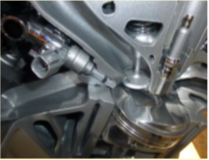 and the resulting mixture is then ignited by a spark plug.
The injection system used on SIDI engines differs from standard fuel injection in one important way. With SIDI, the fuel is injected at a much higher pressure (up to 2,000 psi or higher. or 15,000 kPa) because it’s injected directly into the combustion chamber rather than into the intake manifold (port injection).
–These systems still use a low pressure pump and will pump fuel to the high pressure pump to achieve the higher fuel pressure specifications.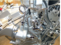
There are several engineering principles involved with this type of injection system. One is the unique shape of the pistons , which will direct the fuel either with a chamber cut into the piston, or by directing the fuel off the combustion chamber walls, to center the fuel mixture directly at the spark plug’s electrode thus resulting in better consumption of the available fuel mixtures. This along with the higher compression ratios give these engines a better performance to fuel mileage ratio.
The one draw back to this system is that it is prone to carbon build up. It isn’t uncommon to have carbon issues causing misfire codes so be sure to sell carbon cleaning services on the upper intake and injectors as often as we once did tune ups! Approximately every 20-25k miles.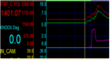
–
Safety notes: High pressure lines are a one time use item. Be sure to relieve the high pressures to avoid personal injury before disassembly by removing the fuel pump relay and cranking the engine.
GDI CLEANING
The number one service issue surrounding gasoline direct injection is the fact that they produce carbon. This carbon forms inside the combustion chambers as well as on the high pressure injector tips. If left unserviced this carbon will often times not only cause engine misfires but may become so bad that it will necessitate engine disassembly to scrape the carbon deposits free from where they are prone to collect. 
The easiest solution to prevent this situation from happening is to perform regular maintenance injector and intake cleaning services. To do this type of service we will need to install the cleaning solution into a centrally located vacuum port such as the canister purge hose or the brake booster hose while the engine is running. Be sure to closely monitor the amount of cleaning solution that is entering the engine to avoid a possible hydrostatic lock up condition from occurring. 
Several reputable companies such as BG and Wynns offer a manual cleaning solvent kit while ATS tools offer a dedicated 3-solution automatic cleaning machine.
Related Course

LBT-406 Evolving Fuel Systems Technology
View CourseThis course presents an overview of automotive fuel delivery systems from early carbureted delivery through today’s efficient but complex injection components. John’s presentation explains diagnostic procedures, standard components, disassembly and reassembly procedures, and safety recommendations for the technician when dealing with possible hazardous situations such as high pressures.


