
The Diagnostic Mindset – Technical Article
March 1, 2021
The Diagnostic Mindset
By John Forro
Lead Instructor, Automotive Video Innovations
This month’s featured course is from AVI instructor Ron Bilyeu, and it covers one of the most important topics regarding diagnostics in the automotive industry today: scan tool PID interpretation. In this first in a series of classes, Ron uses a scan tool by Autel on Ford and Toyota vehicles and gives us those golden nuggets of information as only Ron can.
The most misunderstood concept I have found when conducting training classes is that although a scan tool provides valuable diagnostic information such as codes and data stream PIDS, what the technician may be lacking is the background knowledge needed to diagnose and repair the vehicle successfully using this information. Help with this data interpretation can often be found using an automotive shop’s information system. For a real-world example of this, let’s look at a prevalent scenario that technicians face daily—a misfiring vehicle. While we will be using a scan tool in this scenario and, at times, a scope, we want to focus more on the thought process and the logical steps to take when diagnosing such a complaint. Applying the approach we will be following in this article to other diagnostic scenarios will surely improve your diagnostic skill set.
This example’s key areas will be understanding how the system works, acquiring the necessary data to determine where the problem may lie, then using a common sensed approach on diagnostics to determine the root cause. Remember, the actual diagnostic procedures you choose will often be different from one vehicle to the next, based on the complexity of performing the various vehicles’ tests. There is no one-way golden ticket that you must follow. Instead, it is determining the easiest path, the path of least resistance, to arrive at your destination.
The Misfire Mindset: How Does it Work?
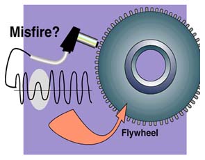
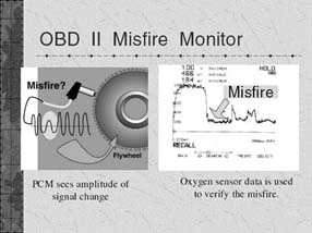
On OBD II vehicles, the misfire monitor is sampling the speed of the crankshaft. When a misfire occurs, the crankshaft slows. Many things can cause the crankshaft to slow, and automotive engineers know this. An example would be an A/C compressor engaging. For this reason, the PCM will not only monitor the crankshaft speed through the RPM sensor but will often look at other sensors as well to verify actual misfires. An example of such a sensor would be the oxygen sensor. If we think about what a misfire is, we can imagine if the air/fuel mixture does not get ignited within the cylinder, when the exhaust valves open, the air gets pushed into the exhaust system. This will cause the sensor(s) to read lean from the extra exhaust present, which did not get used through the act of combustion. The PCM will then have two sensors. The RPM sensor shows a slowing crankshaft revolution, and the oxygen sensor showing the added air present. From these two signals alone, it can accurately determine that a misfire did occur. The misfire event’s severity will determine if a generic P0300 random misfire or a P030x specific cylinder misfire type of code is set! Below is an example of an actual misfire being confirmed using a lab scope.
The Internal Combustion Engine
Now that we know about the PCM’s misfire code, let’s talk about a typical internal combustion engine and its 4-stroke cycles. This will be used to formulate an understanding of why the engineers developed the above strategy for monitoring and setting a misfire code.
The Intake Stroke
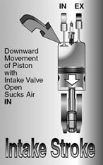
The piston moves down inside the combustion chamber. When this happens, the intake valve is open due to the engine’s camshaft’s mechanical timing having its cam lobe for that cylinder making contact in some way to the tip of the valve stem. The intake valve in the open position and the piston moving downward will cause air and possibly fuel (depending on the fuel system being used) to enter the combustion chamber. This is due to the difference in pressure related to the atmospheric pressure located outside of the engine.
The Compression Stroke
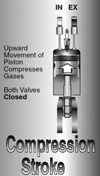
Due to the crankshaft’s spinning inertia, when the piston reaches its most downward position after the intake stroke, it will begin to travel upwards within the combustion chamber. It is important to note that at this time, the high cam lobe will no longer be in contact with the intake valve, and the valve spring will force the valve closed. As the piston moves upward inside the combustion chamber, Both the exhaust and intake valves are closed, causing the air and possibly fuel mixture to be compressed inside the closed chamber. As this happens, physics takes place, and the inside temperature will rise within the cylinder. On a gasoline engine, the manufactures will keep the pressure/heat to a point just shy of auto-ignition. The typical inside combustion chamber’s temperature will be about 1700 degrees Fahrenheit. Any additional heat source will want to ignite the mixture and cause an expanding flame front to occur, forcing the piston downward, creating added energy in the form of inertia to the crankshaft. This inertia will keep the vehicle running and allowing this 4-stroke cycle to be continually repeated on all the remaining cylinders.
The Power Stroke
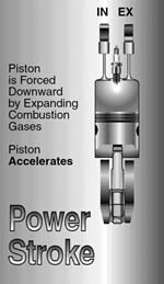
During the power stroke, the ignition coil’s stored energy will be discharged, forcing a spark to be created at the spark plug as that stored energy finds a ground source located at the spark plug’s threads where they screw into the cylinder head. Remember, since the combustion chamber was sitting at a temperature just below auto-ignition, any heat source will ignite that air-fuel mixture! The spark plugs or a hot spot such as carbon build-up (spark knock) will cause the mixture to ignite. Diesel and some gasoline injected vehicles operate differently by raising the inside combustion chamber temperature past the auto-ignition point and then spraying fuel inside the chamber once the piston reaches near the top dead center of the combustion stroke. When these types of vehicles do this, the fuel-air mixture will immediately ignite! Once the air-fuel mixture is ignited, the expanding flame front gasses will cause the piston to be forced down inside the combustion chamber. During this stroke of the engine’s operation, both the intake and exhaust valves are still closed.
The Exhaust Stroke
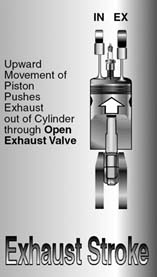
Through the spinning inertia, the crankshaft will now force the piston upward within the combustion chamber. At this time, the camshaft has also rotated, causing the cam lobe’s high point to make contact with the exhaust valve’s stem forcing it to open. As the piston travels upward within the cylinder, the combustion products are forced out of the open exhaust valve and dispersed into the exhaust system setting up the cylinder’s next four-stroke cycle event.
Some Facts and My Beliefs
Now that we understand how the engine works and how the computer senses a misfire, I wanted to share a few factual statements and two personal beliefs:
Fact 1: An engine mechanical issue can cause a misfire.
Fact 2: An ignition malfunction can cause a misfire.
Fact 3: A fuel system malfunction can cause a misfire.
Belief 1: Believe your customer! They are not lonely. If they bring you a vehicle for any reason, including a misfire or poor running type of complaint, or if there are stored misfire codes in it but it now runs well, it has an issue!
Belief 2: There is no one way to diagnose anything. I like to say that several roads in life will take you to your destination. It is up to us to determine which is the most logical route to take.
Diagnosis
Let’s explore how to diagnose a current or an intermittent misfire. Some of these steps below can be shared while diagnosing the intermittent as well.
Special Note: A quick test to perform is to wet down the ignition components with a spray bottle of water. Remember that items fail under load, so road testing or power braking is highly recommended!
The Scan Tool
Besides just pulling DTC’s, the scan tool offers many diagnostic PIDs that can be used to determine the misfire’s cause. Let us take the time to list the key PIDs below:
The Engine Mechanical Tests:
- Mechanical ability to breathe.
- Graph the MAP sensor on the metric scale because you will have a 0-100kpa scale instead of 0-30 hg. The MAP should be steady, not bouncy.
- If Volumetric style, use your vacuum gauge or transducer. Again it should be steady.
Silver Bullet
- If the gauge or MAP graph is bouncy, you are replacing something that contacts oil. No number of plugs, coils, injectors, etc., will fix anything.
Check Volumetric Efficiency (the PIDS below will need to be recorded)
- RPM
- MAF GPS
- IAT/BARO
- WOT
- Plug into a VE calculator and must have over 80% on naturally aspirated engines.
Silver Bullet 2
- Does it have a Load PID? Or a relative charge PID on some import vehicles? If so, this has its own built-in VE test. Must be higher than 90% during WOT test.
- If your results are below 80% threshold or lower than 90 on non-naturally aspirated engines, you need to look at your fuel trim values immediately!
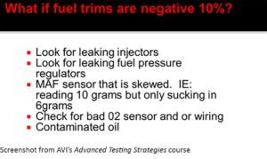
- FT above or below 10% positive or negative, you most likely have a MAF reporting issue.
- If fuel trims are between -10 to +10, you have a breathing issue.
Common Areas of Concern
- Dirty air filter, carbon, timing issue, leaking valves, worn cam(s), cylinder leakage such as rings, restricted exhaust, etc.
Silver Bullet: If normal at idle but once throttle raised, it pegs one bank negative and one bank positive, then suspects a plugged converter on the negative bank. Or a possible valve timing issue.
Silver Bullet: 1 cylinder breathing issue results:
- Speed density: Adds FUEL
- Volumetric: Leans FUEL
- Silver Bullet: If you have a mechanical issue such as a stretched belt/chain that equally affects all cylinders, fuel trims will TEND TO read normal.
If your scan tool can perform the VE test by itself, such as the ATS Elite tool, I highly recommend using this feature to rule out a mechanical issue. Below is an example of such a tool where after plugging in a few informational items listed above, it will display a graph showing what the VE should be compared to the actual VE of the engine.
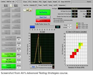
If you fail the VE test, I would suggest using your lab scope to perform a relative compression test, a vacuum waveform test, an exhaust pulse test, a cylinder pressure transducer test, and a crankcase pressure test. Combining these tests will give you the answer as to why the cylinder is misfiring if its root cause is related to an engine mechanical fault.
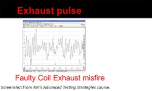
Exhaust Pressure Transducer Testing
A significant first step in overall verification of misfire
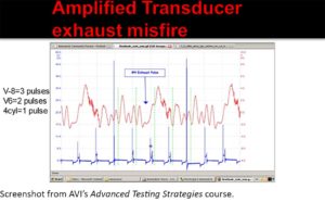
With the trigger set up, use the pulses legend shown above to determine the cylinder with the misfire relating to how many pulses after the trigger event you see. For example, an 8-cylinder engine with the trigger set to number 1 cylinder will be three pulses after the event.
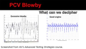
Crankcase Pressure Transducer Testing
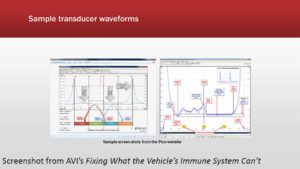
In-Cylinder Transducer Testing: (Best, But Riskiest)
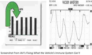
Vacuum Waveform Testing
Below is a transducer hooked to a vacuum line showing a burned exhaust valve on cylinder 3. Also displayed is a relative compression waveform displayed in bar graphs. Note: Your scope will default display relative compression in an amperage type pattern.
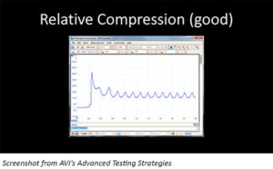
Now let us look at some PIDs That would indicate general issues, whether they be in the fuel system, ignition system, or engine mechanical.
Temperature: (what can this inform us?)
- Rich running
- Restricted exhaust
- Always back up your suspicions!
02’s pre/post (what can I use this for?)
- Misfires
- Fuel Issues
- Vacuum/exhaust Leaks
- Post Cat high greater than 600mv with upstream low or normal=Ignition
- If lower than 200mv =fuel
- Ratio sensors: Pumping current up=lean
- Down=Rich
- Lambda less than 1 is rich.
Fuel trims: (what can I use this for?)
- Rich/lean
- Fuel systems issues
- Effect on the dynamic range!
- Ignition system issues
- Ignition creates minor FT corrections.
- Fuel density creates double-digit corrections.

Mode 6 Testing Strategies
Remember that you have misfire counters in most vehicles, but you always have mode 6 info to help misfire diagnostics. This is great because they give you the testing strategies, so USE those strategies to determine intermittent issues. If it is close to failing but barely passing, that will warrant you taking time to investigate that cylinder testing whether or not the misfire is present at this time!
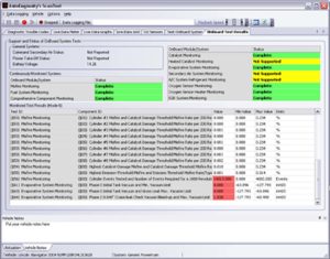
STFT: Normal should be 0. If greater than 5, suspect a vacuum leak or faulty o2 sensor.
LTFT: Normal is plus or minus 10.

Ignition System Primary Patterns Continued
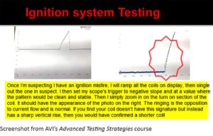
The following slides were taken from an older ignition system testing class that I did before becoming an AVI instructor. The cool thing about these slides is that the concept of ignition system pattern interpretation and diagnostics doesn’t change!
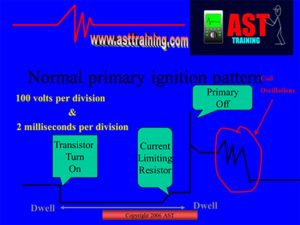
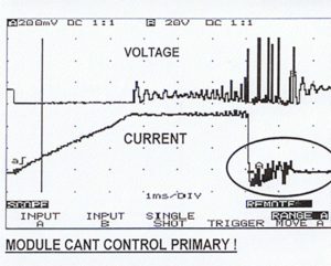
Above, we have both a voltage and amperage pattern of the same coil. This coil can not control the primary current flow! More importantly, however, is the part of the waveform I have circled. If you see this happening, this is an indication of a secondary ignition issue! (plugs.wires.boots etc.)
The Secondary Pattern
(most likely today, you will be using a paddle probe)
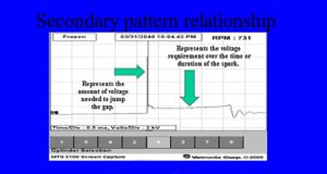


Spark line sloping up Indicates Lean!
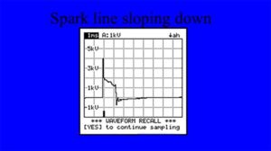
Spark Line sloping down indicates a rich condition.
Remember, a misfire will also affect the gas emissions if you should happen to have a gas analyzer. Also, remember that a misfire is the number 1 thing that kills a catalytic converter.
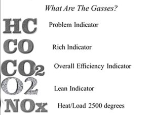
Using the above descriptions, your indicator that a vehicle is misfiring will be HC! Since you verified the misfire is present, look to 02 and C0 to determine if the cause is fuel or ignition-related. If it’s fuel-related, then C0 will be high, while 02 would be high if it’s the ignition!
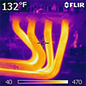
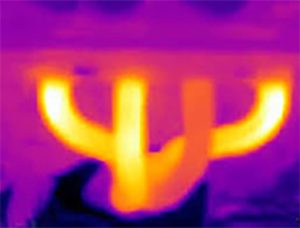
Finally, another easy tool one can use to determine which cylinder is misfiring is a temperature gun. Like your oxy-acetylene torches, it will turn the flame hotter when there is more oxygen present than other cylinders. Below are two examples of using this type of tool to help determine the offending cylinder. The first is expected, while the second clearly shows an issue is occurring since there is not as much heat present since combustion has not happened.
Final Notes
As you can see, the article you just read had no highly coveted trade secrets. It instead covered a basic common sensed approach to diagnosing a prevalent trouble code within the automotive industry. There is no better way to approach diagnostics than first to understand how the system is supposed to work, then gather necessary diagnostic test results in the most common-sensed way imaginable to finally arrive at the diagnostic conclusion. We hope you have found this article helpful and look forward to seeing you in upcoming AVI training events and classes.
Related Course

Computer Engine Data Interpretation – Ford & Toyota
View CoursePresented by Master Mechanic Ron Bilyeu and focusing on Toyota and Ford scan data, the presentation drills down deep into both prominent and obscure PIDs, explaining the valuable content they show. Information on air/fuel ratios, knock sensors, idle evaluation, misfires, VVT, and crankcase pressure measuring is only a small part of the information presented.

