Diagnostic Dilemmas: Approaching No-Code Diagnostics
March 26, 2013

1997 Toyota Camry
Thanks to the increasing reliability of modern vehicles, most diagnostic technicians are seeing fewer pattern-failure driveability complaints.
For that reason, many techs won’t gamble expensive shop time chasing an illusive no-code driveability complaint.
Instead, many will write “no problem found” on the repair order and move on to the next vehicle.
Unfortunately, at some point in time, the intermittent, no-code driveability will either be solved or the vehicle will be traded or sold for scrap. This month’s Diagnostic Dilemma will discuss in detail how I approached the no-code, intermittent driveability complaint on three
different vehicles.
The Stalling Camry
Last summer, I encountered a customer with a no-code, intermittent stalling complaint on a 1997 Toyota Camry. According to the customer, the stall most often occurred during engine warm-up or would manifest itself as an occasional hesitation at road speeds.

Photo 1: The ECT (green connector) appeared to be a frequent culprit in many stalling complaints.
Although well-maintained, this vehicle had rolled up in excess of 200,000 miles. At this point, the crankshaft position (CKP) sensor had been replaced with no result.
While I don’t believe in searching for silver bullets, I do believe in doing preliminary research by consulting a professional database for technical and anecdotal case-study information.
It didn’t take but a few minutes online to determine that a faulty engine coolant temperature sensor (ECT) was causing many Camry stalling complaints.
The simplest procedure might have been to replace the relatively inexpensive ECT and let the customer drive the vehicle to verify the repair.

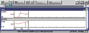
Photo 2: Notice that, as the indicated coolant temperature plunges to -4° F, the data graph indicates a small but sharp dip in engine speed.
But, because just about any other component in the engine management system could also cause a similar stalling complaint, I decided to pursue a more complete diagnosis.
As part of my Standard Operating Procedure, I cleaned the throttle plate assembly with throttle plate cleaner with a toothbrush and followed up with solvent-penetrating oil that lubricates the throttle plate and bore.
Next, I tested the battery for state of charge (SOC) and state of health (SOH), and checked the voltage drop at both battery terminals.
Although the battery terminals passed both tests with less than a 0.5-volt drop, it’s important to remember that the terminal-to-cable connection on Toyota battery cables can conceal severe corrosion, so I physically took these connections apart and cleaned those surfaces.
I also physically inspected the ECT sensor, throttle position (TP) sensor and idle air control (IAC) connections and used the graphing feature on my scan tool to wiggle-test each circuit to verify that these sensors didn’t have any broken wires.
Before starting the engine, I connected my scan tool to the Toyota so I could record coolant temperature on the data graph.
Luckily, I felt the engine “hiccup” as it warmed up and pushed the “save” button on my scan tool to store the image. After recovering from that minor stall, the engine ran without fail for another 30 minutes.
As Photo 2 indicates, the indicated ECT plunged from +14° F to -4° F for just a few milliseconds, with the engine rpm dropping a few rpm as well. For me, this was the smoking gun that proved the ECT sensor was at fault. At that point, I replaced the ECT sensor and asked the owner to report back if he had another stalling problem.
So why wasn’t an ECT-related diagnostic trouble code (DTC) stored in the PCM’s diagnostic memory? Let’s keep in mind that any failure must meet the enabling criteria required to store an applicable DTC. Because seven different generic ECT-related codes are listed for this application, I can’t list their enabling criteria in this space. But, while this glitch didn’t last long enough to store a code, it did last long enough to richen the air/fuel mixture ratio and stall the engine at idle speed.

1996 Jeep Cherokee
The Stalling Cherokee
While the engine management technology on a 1996 Jeep Cherokee might be obsolete, the
diagnostic methods used to find the cause of an intermittent, no-code stalling complaint are not.
What makes this case unusual is that the Jeep is a right-hand-drive model driven by an independent contractor on a daily rural free delivery mail route.
Given the replacement cost for a right-hand-drive vehicle, the owner elected to spend whatever it might cost to keep this Jeep running.
Off the top, the Jeep had a new TP sensor, IAC valve, new ignition coil and remanufactured distributor installed, presumably to remedy the stalling complaint.

Photo 3: This waveform illustrates a perfect cam/crank synchronization on a Jeep 4.0L engine.
All of the above indicated that the problem might turn out to be a real head-scratcher, which it proved to be.
Once the vehicle was warmed up, it might be driven for hours without stalling. Other times, the stalling complaint occurred so frequently that the vehicle was impossible to drive.
After I began testing, the engine idled from a cold-soak for 30 minutes and then stalled.
Thanks to my long experience with Jeep systems, I had a two-channel lab scope connected and ready to record the CKP and camshaft position (CMP) sensor waveforms.
Photo 3 illustrates the correct relationship between the CKP and CMP sensors. Notice that the green trace at the top is the CMP sensor, which indicates whether the No. 1 cylinder is on a compression TDC or exhaust TDC stroke.

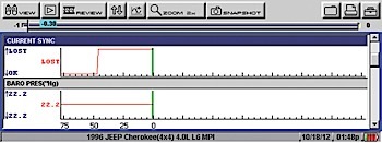
Photo 4: Although the baro pressure is irrelevant to the diagnosis, the loss of the cam/crank sensor synchronization is extremely important.
Notice also that the CMP “on” signal below covers four Hall sensor signals indicating the positions of three cylinders while the remaining three cylinders are covered by the “off” CMP signal.
Needless to say, the CMP signal went straight-line when the engine stalled.
Since remanufactured distributors can have their problems, I elected to replace the Hall sensor with a premium-brand CMP sensor. In doing that, I also recognized that the failed CMP sensor was a secondary, rather than primary, cause of the stalling complaint.
I might add that, because it takes about 20-30 minutes for the distributor to reach engine temperature, this time period alone was enough to make me suspect that the CMP sensor was failing.
After I replaced the faulty CMP sensor, the engine again stalled after about an hour of running time. Here

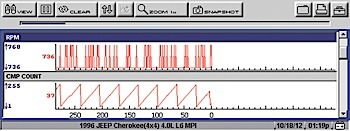
Photo 5: Notice the disappearance of rpm and the declining CMP count as the engine begins to stall.
Again, I’m guessing that the stall might be caused by a temperature-related failure in one or more components. Since I couldn’t establish a relationship between the PCM’s temperature and the stalling complaint, I began to suspect the CKP sensor.
Since a visual inspection revealed that the CKP sensor had recently been replaced, I began to look a little deeper for the cause of the stalling complaint. For example, the PCM had reached about 130° F hot-soak temperature.
At this point, I removed the PCM connector to check for possible corrosion. Before reassembling, I coated the connector pins with some Stabilant-22 connectivity-enhancing agent and cleaned all chassis grounds and both battery terminals. I also verified the battery’s SOC and SOH.
I was certain that the stalling problem wasn’t being caused by the IAC valve because I could hear a noisy sucking sound as the IAC began to open up as the engine stalled.
I also believed that the throttle sensor wasn’t at fault because, in most cases, an erratic TP sensor voltage at idle will cause the PCM to increase, rather than decrease, engine idle speed. Nevertheless, since the IAC and TP circuits share a ground circuit on this application, I connected a DVOM set at the min/max function to record any discrepancies in the TP ground.
As with the previously mentioned Toyota Camry, the most valuable tool in locating potential wiring faults and sensor failures is the data graphing feature included in most scan tools. In this case, I monitored the synchronization between the CMP and CKP sensors.
As shown in the data capture in Photo 4, a loss of cam/crank sensor synchronization is extremely important because it indicates that the CKP sensor might be momentarily failing to synchronize with the CMP sensor. Although a two-channel lab scope and scan tool was connected to the engine to record cam/crank sensor data, it was extremely difficult to capture the failure as it occurred.
In any case, the suspected CKP failure happened so quickly that I couldn’t capture it on either tool. I experimented with setting my lab scope on normal trigger and still had a normal cam/crank synch pattern at the time of failure.
But there were clues. First, the stalling condition required about an hour of warm-up time from an overnight cold-soak. Second, each stalling incident included a loss of cam/crank synch. So I speculated that it might take about an hour for the CKP sensor located on the bell housing to warm up from cold-soak to engine temperature.
Keep in mind that, because the failure occurred only after an hour running time from cold-soak, this testing procedure was becoming very time-consuming.
I will say that I am equipped to deal with this type of diagnostic scenario more so than a technician working in a production situation. Once I understood the time frame, I could warm the engine up and work on other projects. But, at some point, it’s also mathematically cheaper to replace suspect parts than to test to the point of failure.
So at this point, I replaced the CKP sensor and ran the Jeep through several more warm-up cycles. Here again, I’m not sure that the PCM was programmed to recognize a CKP glitch that evidently occurred just for a few milliseconds. Fortunately, the engine didn’t stall during several cold-soak warm-ups. Because several road tests also confirmed a no-stall condition, the vehicle was delivered to the customer and, presumably, it’s still running just fine.

2002 Ford Mustang
No-Code Mustang Misfire
Let’s take a brief look at a no-code misfire complaint on a 2002 Mustang equipped with the 3.8L engine and automatic transmission and with about 120,000 miles on the odometer.
Because this car belonged to a young, do-it-yourselfer friend of mine, I recommended that he bring his maintenance up to date by installing new spark plugs and wires. None of that, of course, solved the misfiring complaint.
Fortunately, my friend claimed that his Mustang misfired most frequently as throttle was applied from a 60 mph cruise condition when climbing a nearby hill. At wide-open throttle (WOT), the misfire would disappear. Long story short, I verified the identical symptoms and recorded exactly 41 misfires during the half-mile climb up the hill.
As most of us know, misfires can be caused by fuel, ignition, compression and timing problems. In this case, the seat-of-my-pants indicated a bad secondary misfire. One diagnostic scenario is that the misfire occurs only at part-throttle because the air/fuel (A/F) mixture ratio is transitioning from lean to rich. A contributing reason is that the running compression in the cylinders increases as the throttle is opened.
So, during lean cruise, the engine doesn’t build enough cylinder pressure to cause the misfire, but, as the throttle is opened, the lean A/F mixture begins to increase firing voltages. Once the throttle reaches WOT, the fuel mixture richens enough to reduce firing voltages and eliminate the misfire.

Photo 6: This Mustang had an obvious part-throttle misfire problem, but no P0300-series code to go with it.
The reason no misfire codes were stored is that 41 misfires during a half-mile interval isn’t enough to store a P0300-series DTC. So after returning to the shop, current-ramping the ignition coils indicated no failures in the primary ignition circuits or drivers.
At this point, I’m speculating that the waste-spark ignition coil has a potting failure in the epoxy compound used to insulate the coil windings and form the coil body. So the coil developed an internal short that was sensitive to spark demand created by both running compression and air/fuel mixture ratio. A new coil fixed this intermittent, no-code misfire complaint.
cutlines

