
Parasitic Battery Drains
June 24, 2014
By Dave Hobbs. Para What? It’s amazing how many IATN posts I see with good techs struggling in the area of parasitic battery drains. How much is too much? How to test? I guess I shouldn’t be amazed. I literally grew up in the family auto electric shop and this kind of thing was our bread and butter. For the rest of the shops out there who have to be experts in everything from the turn signals to the transmission, it can be a bit confusing. So what is a parasitic battery drain?
In review and in automotive terms, a parasitic drain is an electrical load that draws current from the battery when the ignition is turned off. Some are considered normal, some above normal. Regarding what’s normal, we have the various electronic devices sometimes “affectionately” referred to as F.R.E.D.s. (Frustrating Ridiculous Electronic Device) connected to hot all the time battery power circuits ebbing away in tiny amounts on the battery. FREDs often draw a few mA (milliamps) because of something called KAM. (Keep Alive Memory) Whether it’s the clock in the radio or the last known position of the memory mirrors, these tiny amounts of KAM induced current typically will only add up to 20 or 30 mA at most. That means the vehicle can sit parked for days, even a few weeks without any problems of excessive battery drain that might prevent starting. As long as the vehicle is driven periodically in order for the alternator to recharge the battery there is no problem. A problem may occur, however, in situations such as new vehicles in dealer stock, long term airport parking situations, the driver who parks the sports car for the winter or the retiree who leaves their “northern car” parked in the garage while a second car gets used in more winter friendly place, like say…Fort Myers Beach Florida. Not a bad idea if you ask me! To get down to really “techie” terms, you can calculate just exactly how long your customer’s battery will keep it’s head above water, electrolyte-ly speaking of course. It all boils down to the actual parasitic drain, the reserve capacity (in minutes) of the vehicle’s battery and the amount of parking time.
As noted in a typical TSB for a late model GM vehicle, the Reserve Capacity (RC) rating multiplied by 0.6 gives the approximate available ampere-hours (AH) from full charge to complete rundown. Somewhere between full charge and complete rundown, the battery will reach a point at which it can no power the starter. Using up about 40% of the total available AH will usually take a fully-charged battery to a no-start condition at moderate temps of 25°C (77°F). Put another way, for a typical battery in a storage situation, depleting the available AH by 20 to 30 AH will result in a no-start situation.
Important: If the battery begins storage at 90% of full charge, reduce the available AH accordingly.
Although the maximum rule of thumb recommended parasitic drain is around 30 mA (0.030 amps) a typical drain usually falls into the 7-12 mA range, even though some luxury vehicles do approach the maximum. Multiply the drain (in amps) by the time (in hours) the battery sits without being recharged. The result is the amount of AH consumed by the parasitic drain. The actual drain may be small, but over time the battery grows steadily weaker.
Here’s an example: A vehicle with a 30 mA drain and a fully-charged 70 RC battery will last 3 weeks. But if that battery is at only 65% of full charge it is going to last only 2 weeks before giving the customer that “click click click” complaint. The parasitic drain will be fairly constant over a range of temperatures. The important temperature is that of the vehicle at the time a start is attempted. Colder temperature raises the threshold of a no-start by increasing the residual power needed. When the temperature falls to 0°C (32°F), the battery will be able to put out only about 85% of its normally available starting power, and the engine may need as much as 165% of the usual power to start. The combined effect of these two factors is to reduce the number of days the battery can put up with a parasitic drain. At 0°C (32°F), the battery can last only half as long as it could at 25°C (77°F). And at -19°C (0°F), the days are reduced to 25 percent of the days it could have lasted in warmer temperatures. Now go the other direction, and summer days of 25°C (77°F) or greater increase the battery’s self discharge. If the vehicle is located where the temperature is averaging 32°C (90°F), an additional 5% to 10% of the available ampere-hours will be lost in a month due to self-discharge within the battery. At temperatures below the moderate range, self-discharge is unnoticeable compared to the parasitic loss.
How much should each module’s parasitic drain be on the battery? While following chart certainly is not a set of exact specifications to pass or fail “FREDs” it does give good estimates for the parasitic drains of various devices.

How to Test
Testing for parasitic battery drains has changed a lot since my dad taught me to connect a test light in series with the battery cable in the 1970’s. The theory then (and it still applies today) was that a large parasitic drain would cause the test light to glow brightly, and a small drain would either not light the bulb or only light it very dimly. Not exactly accurate, but effective before FREDs starting showing up in large numbers on the vehicle. Most test lights would require more than 500 mA to flowing through the circuit they were tied into to glow, and pre-FRED cars didn’t really have any non parasitic drains that didn’t draw enough power to light the test lamp. Even the glove box light or trunk light staying on would light the test lamp. By the way, here is a Mr. Obvious trick (FREDs or no FREDs) to test to see if these lights are actually turning off when they’re supposed to be off…open the trunk or glove box really fast and touch the bulb. If it’s hot, obviously it’s been burning longer than the second it took to open the lid and touch it. I must warn you…if it has been staying turned on it’ll be almost as hot as McDonald’s coffee and will burn you….so no lawsuits please! 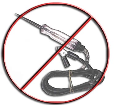 For the trunk light, you could hop in the trunk and have a friend close the lid while you watch the light go off. Make sure your friend has the key, not you, Mr. Obvious warns! Oh, now I’m really asking for a lawsuit, right? Looking back on the test light procedure, this test became ineffective when some of the newer solid state modules would stay powered up and draw 300-400 mA. This did not necessarily make the test light glow, but almost always ran the battery down in a few days. The 1980’s came around and the test light parasitic test gave way to the DVOM’s ammeter connected in series with the battery cable.
Problems With Meters
That test was great…if the problem was present when you connected the battery cable into series with the meter…and if you had a good fuse in the meter…and you didn’t forget and leave the meter in series with the cable when you opened the door (a 2 amp dome light trying to make it’s circuit path through a ½ amp meter fuse) or worse yet, tried to start the engine. The latter scenario would be a starter trying to source 200 amps through the meter’s ½ amp fuse. You could connect the meter leads into the battery cable circuit via the meter’s 10 amp ammeter circuit and it least it could source the dome light when you opened the door without a problem. If you did forget and try to start the engine, you might see the meter’s 10 amp fuse pop or you might be looking at a toasted meter. Some meters don’t fuse their higher current ammeter section. Often times, as in the case of Fluke, the fuses for both the low current (300 mA) and high current (10 amps) sections are fused. The problem is, the fuses are expensive relatively hard to locate.
Solutions to Meter Problems
Here is the solution to all of this…just connect an inline fuse into series with your meter’s leads. Have a fuse slightly smaller than your meter’s low end rating (200 mA) when you are testing for low current parasitic drains and another inline fuse dedicated to putting in series with your meter’s leads when it’s in the high current setting (8 amps) so that if you do a no-no and open the door or crank the motor, you only have to replace an automotive fuse and not an exotic and expensive Fluke fuse or a very expensive meter! If you think this sounds like a hassle…it is. 
 The alternative is of course a low current inductive amp probe.
Beware of the inductive amp probe. It must be accurate enough to measure current as low as 10 mA, which would be a realistic normal parasitic current draw for some vehicles.
MacGyver To The Rescue!
If your probe is accurate down to 100 mA, then you could be a regular MacGyver and make your own current multiplier by wrapping a piece of wire around a soda can 10 times. After you have made the loop, leave a foot or so of wire in each end of the can (to work with later) and remove the can from the loop. Tape up your newly made coil and put some alligator clips on each end. Now you can put that coil into the loop into series with the battery cable. Don’t forget to fuse it so you won’t melt it with an accidental starter motor actuation. Now you can clamp your “accurate down to 100 mA” inductive amp probe around your new coil and you have an “accurate down to 10 mA” inductive amp probe.
More Test Problems…Phantom Drains
Every test mentioned to this point (with the exception of the extreme low current inductive amp probe) has one major drawback…you have to disconnect the battery in order to connect the meter and/or 10X multiplier. If there is a high resistance short circuit (chaffed insulation) causing the excessive battery drain or a leaky alternator diode, or even a light bult staying turned on, no problem. You reconnect your meter into series with the battery cable and read the meter. After a reasonable amount of time (see chart 1) for “FREDs” to power down, you observe that the meter reads 650 mA (for example) and you begin icsolating the circuit the drain is on by pulling fuses one at a time and continuing to observe the current draw measured by the meter. You pull fuse 17 (for example) and the meter now shows 12 mA which seems like a normally acceptable parasitic current draw. Now you look into what items are on fuse 17 and track down the culprit…a bad automatic load leveling height sensor (for example) trying to keep the air suspension compressor turned on. That’s ideal world and it does happen that way sometimes. If Murphy’s law is not on your side that day, you will most likely see 12 mA of battery drain when you connect your meter into series with the battery cable. But the battery is going dead in 3-4 days and the alternator checks good as well as the battery’s condition. Why do you have so much of a problem catching the phantom battery drain? Well, do you ever watch those reality TV shows about the police? When they do a raid on a house, do they give the bad guys advance notice that they intend to serve a warranty or do they sneak up and smash their way into the house yelling “search warrant”? The latter, right? You need to do the same. When “FREDs” are completely powered down and then back up, the more often than not, will NOT latch on in the powered up state for you to diagnose. They may take some “persuasion” to stay powered up. Persuasion like turning the ignition on and off repeatedly or even road testing the vehicle to duplicate the conditions that caused the drain to begin with. You need a plan to catch them in the act of draining the battery. You need a parasitic battery drain tool.
If you are not inclined the spend the $70 bucks for one of these from the tool truck, just bop on down to the local parts or RV store and pick up a battery disconnect switch, sometimes also referred to as a RV knife switch. Connect the switch into series between the negative battery cable and post as shown in figure 5.
Next, with the high current battery disconnect switch closed, drive the vehicle and operate as many accessories as possible in order to duplicate the conditions that might be causing the battery drain. Now, connect your ammeter with its in-line fuse across each side of the closed battery disconnect switch as shown in figure 5. Use the higher current section of the meter at first to make sure the drain is not larger that the lower rated section of the meter. Turn the meter on after a reasonable amount of time has past (see chart 1) for the various modules to power down. Finally open the battery disconnect switch. Now the current flow instead of passing through the switch will pass through the meter. The important thing to realize is that you didn’t have to disconnect the battery (and “tip off” those sneaky “FREDs”) in order to run the ammeter. The disconnect switch simply changed the paths of the current flow. Now observe for larger than normal current draw readings on the meter and narrow down the list of possible culprits by pulling fuses as discussed earlier. It is important to note that sometimes the wait for certain devices to turn off on their own can be fairly lengthy. One series of late model GM SUV’s for example has a HVAC control head that takes up to 4 hours to power down! Who wants to wait around that long for it to go to sleep? One alternative there would be to pull its fuse to ensure that it is the only larger than normal parasitic drain on the vehicle. Then plug its fuse back in, reconnect the battery to the cable, (via the disconnect switch) go do something else productive for a few hours, and recheck the overall vehicle drain later in the day.
Catching Even Sneakier “FREDs”
You may need more than the battery disconnect switch for some stubborn cases. You may need to watch the meter for an extended period of time to see if any solid state modules are waking up and drawing excess current. But who has time to baby sit their ammeter? In the case of a GM vehicle with a class 2 data bus, if you have a Tech 2 scanner, you have the ultimate “FRED baby sitter” ready to work while you make money on something else. It’s rather simple yet ingenious to do. First, set up your phantom parasitic drain test via the battery disconnect and ammeter arrangement mentioned previously. Next, remove the fuse that powers pin 16 of the DLC (12 volt supply for your scanner) so that when you connect your Tech 2, you won’t be seeing its power demand on the ammeter. The fuse is often the same fuse as the 12 volt accessory / cigar lighter fuse. Now, power your Tech 2 with an alternative power source such as the 110V / 12V power supply that comes with the tool. Finally, build the vehicle with the Tech 2 setup menu. When you get to the main diagnostic menu (Powertrain / Body / Chassis / Diagnostic Circuit Check) select Diagnostic Circuit Check.  From there you can go into Class 2 Message Monitor and see all the modules that are on the bus. Turn the ignition switch on one last time (with the battery disconnect switch closed) and watch the state listed next to each module on the bus display the word “Active”. Next to the word “Active will be an odd number like 1, 3, 5, etc. Turn the ignition off and watch the states for the modules to all go to “Inactive”. It may take a few seconds / minutes. (See figure 6) As they do, their previous odd number (1 for example) will increment up to an even number (2) as each “FRED” goes to sleep on the bus and quits drawing any more current than the typical KAM current. (Chart 1) Each module if it was a “2” next to the status of “Inactive” should remain a 2. You can now monitor bus activity by watching module status on the Tech 2. If a module won’t go to “Inactive” (sleep state) or wakes back up to “Active” state (along with a state number change) you may well have narrowed down your problem.
Since the BCM is usually the bus power mode master device you may see it wake up first followed by other modules it might be waking up. The Tech 2 even allows you to put the modules all to sleep to hurry up the process in testing. You can also leave the Tech 2 alone and allow it to monitor the status of the bus. If you leave the Tech 2 “baby sitting” the vehicle while you are off on another job and come back to find that the Driver Door Module (for example) incremented it’s status number from a 2 (Inactive) to a 6 (still inactive) you can guess what happened…the Driver Door Module (DDM) woke up (the status would have incremented to a 3) and went back to sleep (now a 4) and then woke up still yet another time (now a 5) and finally went back to sleep, which gave it the status of “Inactive” but at 6 which you now see on the tool. Keep in mind, an OnStar may need to turn on and wake up periodically due to the nature of its mission on the vehicle, but something like a DDM shouldn’t be waking up unless you touch the door handle or wake up the RKE. (Remote Keyless Entry) Pretty sneaky, that blasted DDM. But not sneaky enough to out smart the Tech 2! And the best part is you let the Tech 2 do the job while you worked on something else. Now that’s what I call “sharpening the saw”!
Hopefully your skills are sharper from this review of parasitic battery drain testing along with these tips that maybe are brand new to you. And even more importantly, I am hoping tonight you can actually go home at 5 o’clock (with a decent day’s wage in your pocket) to do those things that really matter most to you!
Related Course

LBT-270 Parasitic Current Draw with Dave Hobbs
View CourseIn this video, AVI teams up with Delphi instructor and electrical mastermind, Dave Hobbs to bring you the most comprehensive class on parasitic battery drains on the market. Dave will guide you through the entire diagnosis process, step by step and in order to make sure you have confirmed the customer complaint all the way to verifying the repair.
Learn how to use various meters and switches, understand their application and function with clear and precise instructions. Make sense of Amps, volts and ohms while learning to convert them into smaller values like milliamps and millivolts; making the diagnosis process more accurate and precise. Most importantly, learn how to diagnose a vehicle right the first time avoiding costly mistakes and time melting road blocks.

